
Goal:
The goal of the project is to create an internet connected device, that can monitor a batteries voltage, AH, WH, and amperage, at a remote site and have the ability to log data, and be able to send alerts based on the data collected.
How it Works
The IP Watt Meter has two main components a Raspberry Pi and an Arduino. The Arduino uses a voltage divider to calculate the voltage on the battery and an ACS712 voltage sensor to detect the amperage. It then prints it out the data to a serial connection. The Raspberry Pi connects to the Arduino on the serial connection and stores the data inside a MySQL database. It can then take this data and display it on a webpage. The Pi also provides the IP watt meter with an internet connection so the voltage of the battery can be monitored from anywhere and notifications can be sent when something like the voltage is low.
Parts List
- Raspberry Pi with SD card – $40
- Arduino Mini – $9.95
- ACS712 voltage sensor – $7.95
- Red, Yellow, and Green LED’s – $2.95
- 2x 2.2k Resistor
- 1x 4.7k Resistor
- 1x 1k Resistor
- 2x 220 Capacitors
- Wire screw down terminals – $1.90
- Female Headers – $1.50
- Break Away Headers – $1.50
- Solder-able Breadboard – $2.95
- Jumper Wire Kit – $6.95
Building:
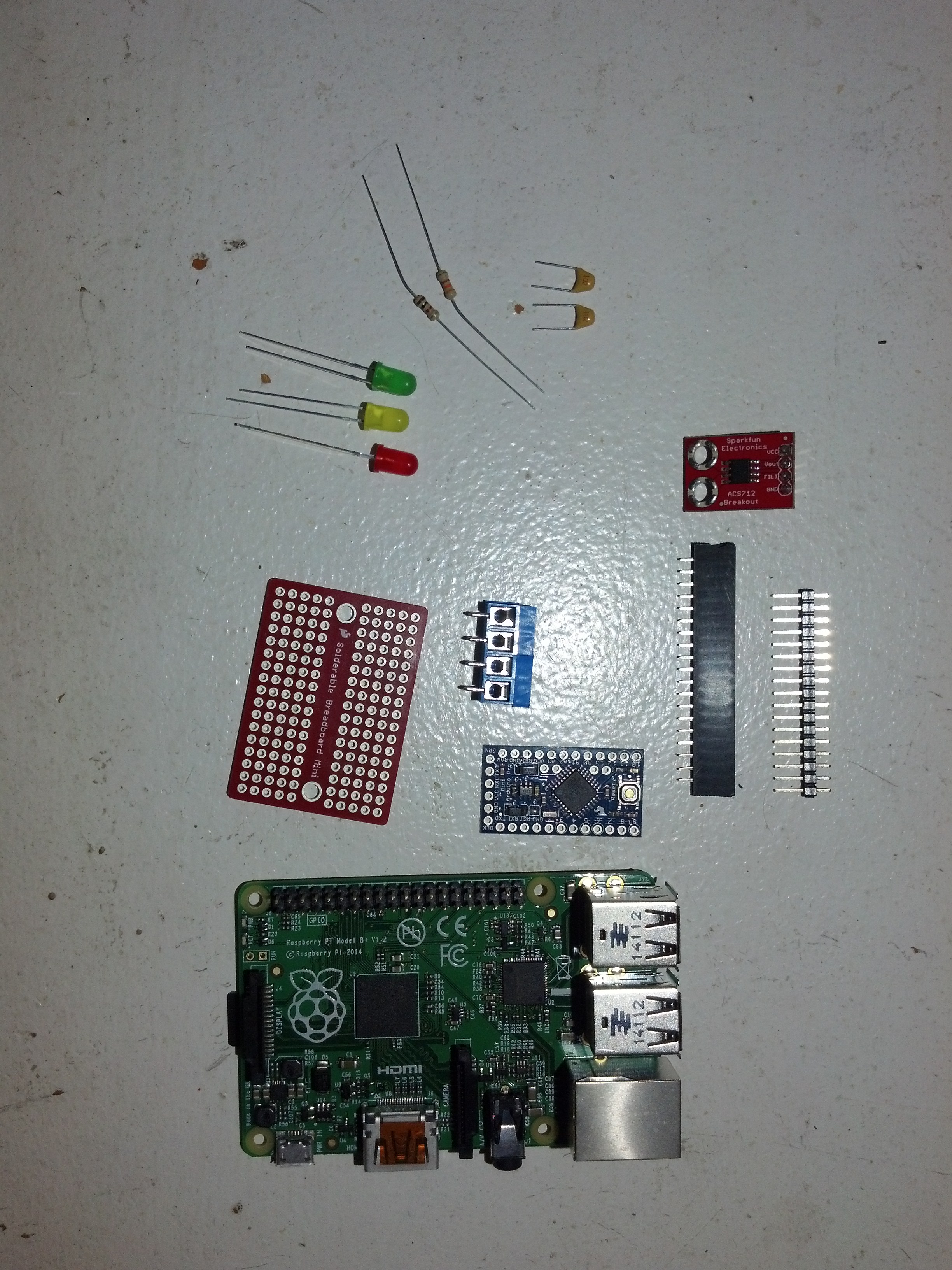
Here are some pictures that were taken during the build process.
Parts used
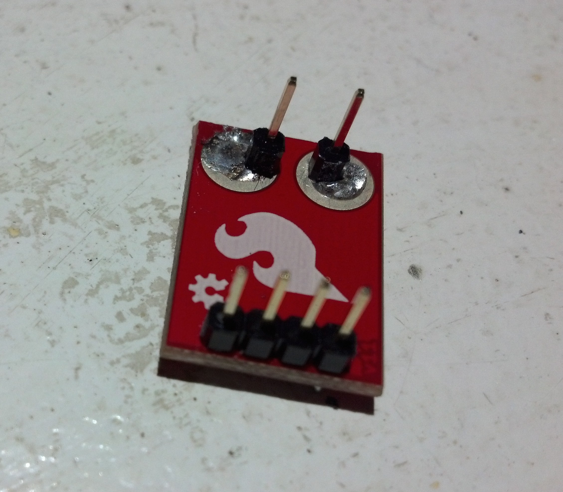
ACS712 Sensor with headers soldered in.
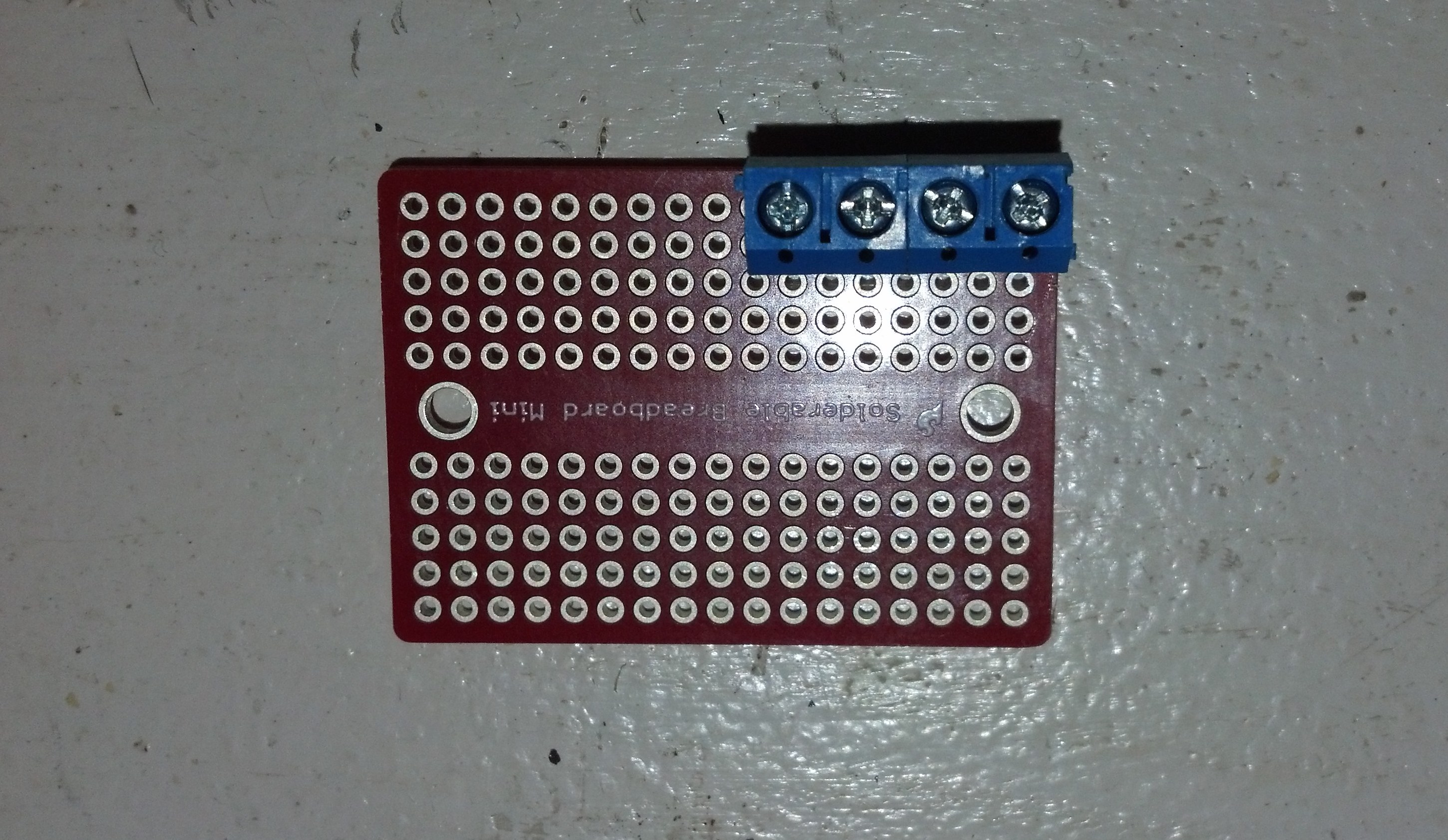
Wire Terminals soldered on board. The two terminals on the right side are the input. The other two are output. The positive wires go in the middle two terminals. The ground connects to the two on the outside. See last picture.
These headers are where the ACS712 Sensor is going to go.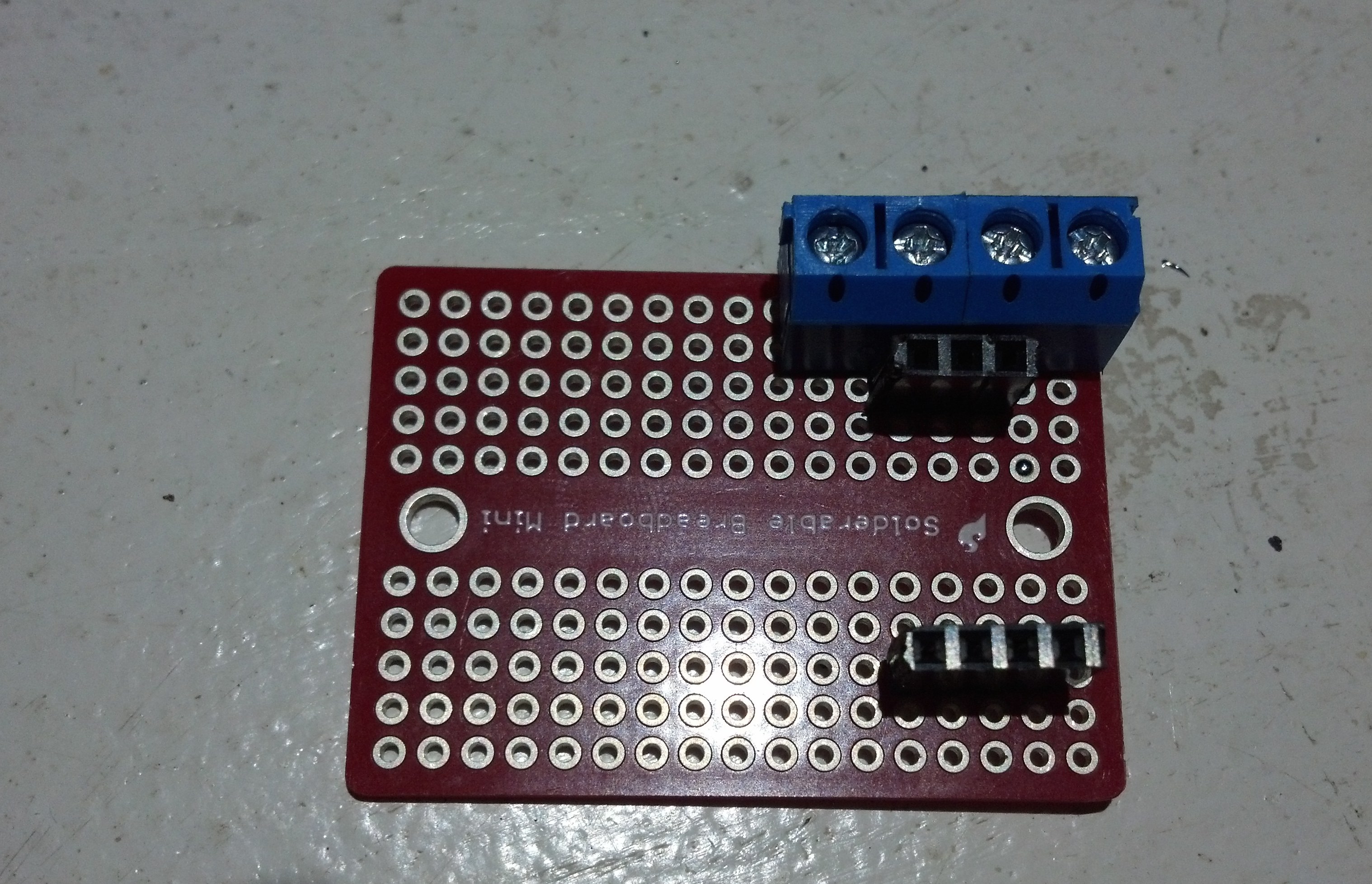
Voltage divider with 2 resistors.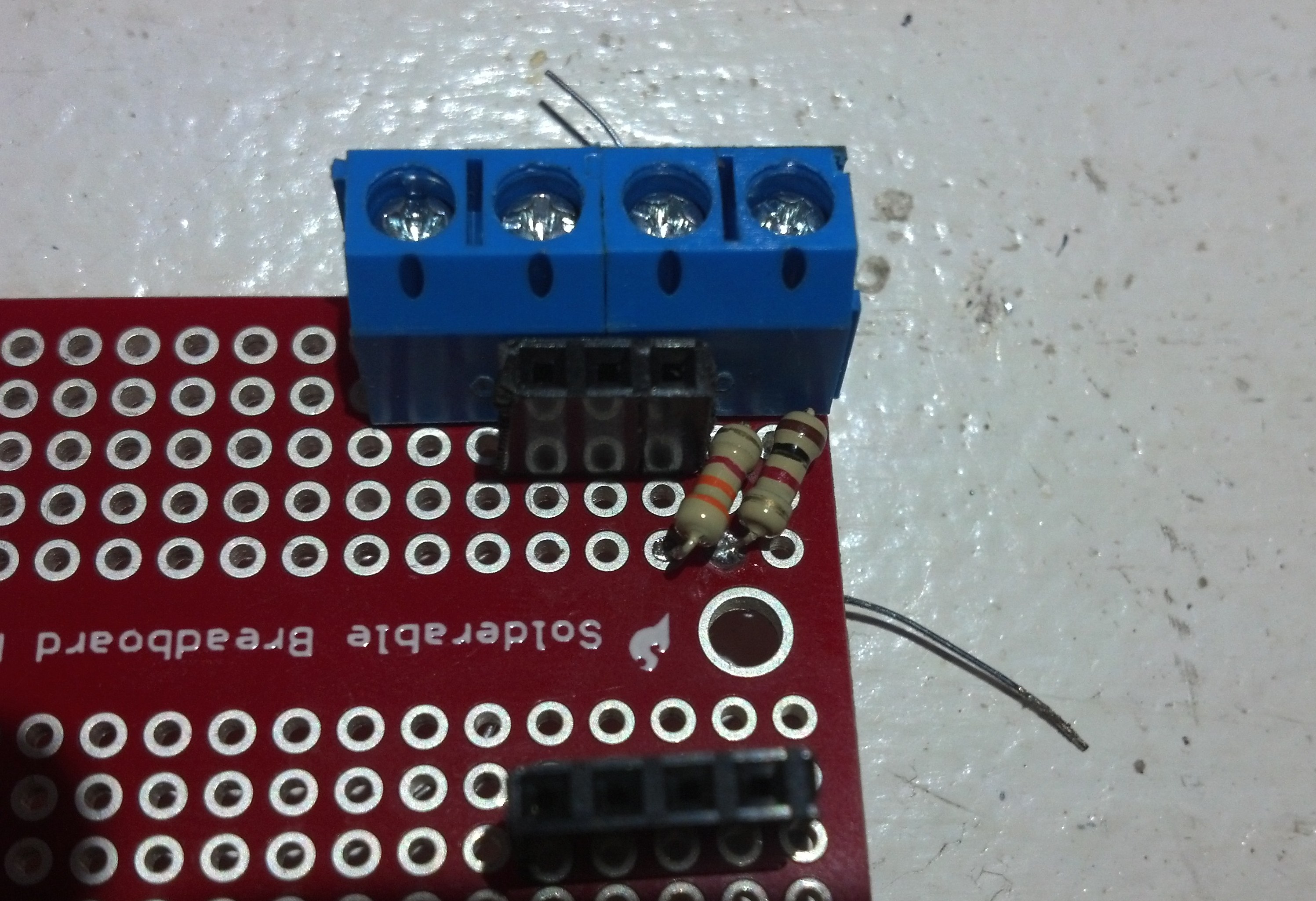
This wire connects the Arduino to the voltage divider so the Arduino can read the voltage.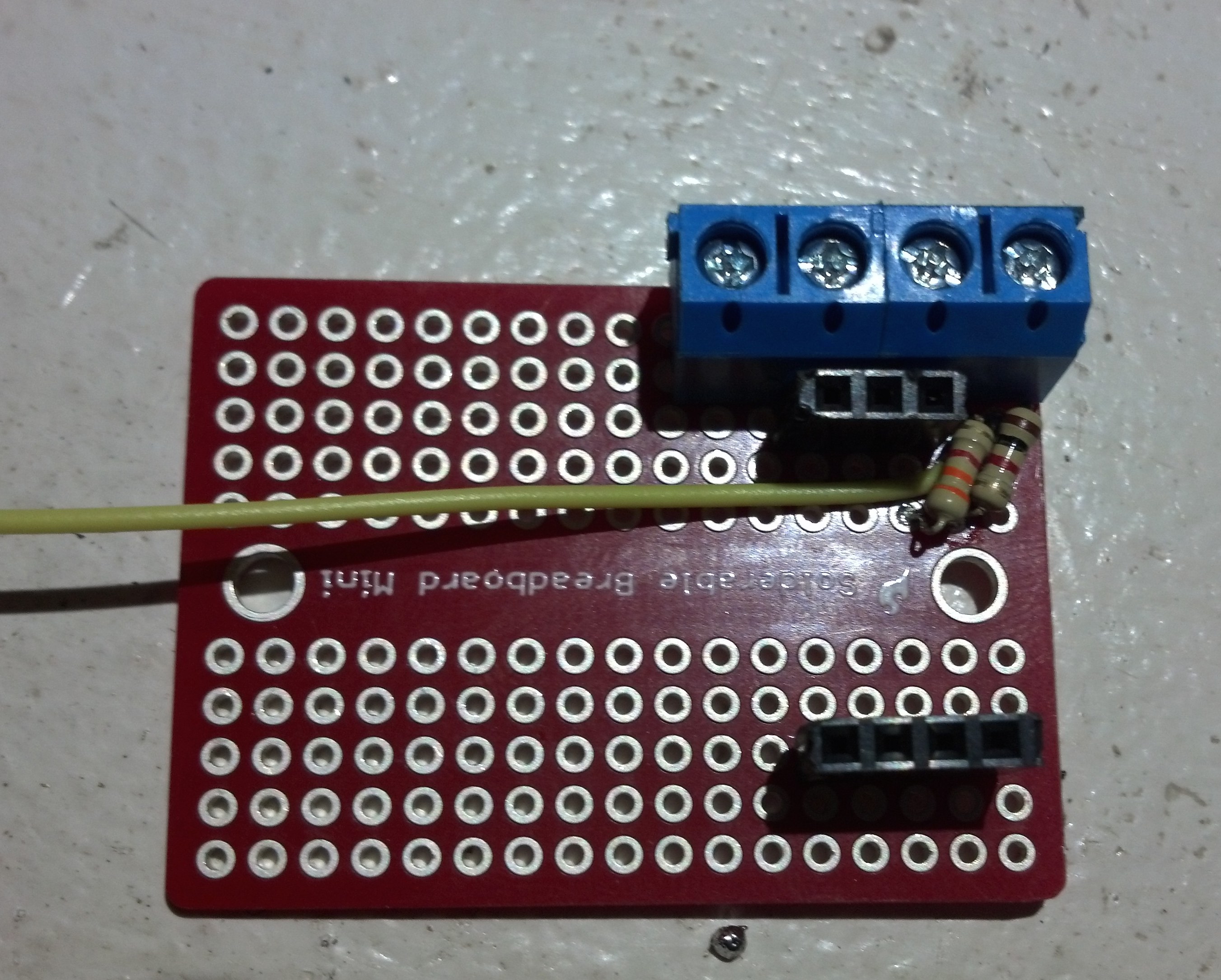
Added some headers for the Arduino. The yellow wire will connect to the second analog port(A2) on the Arduino.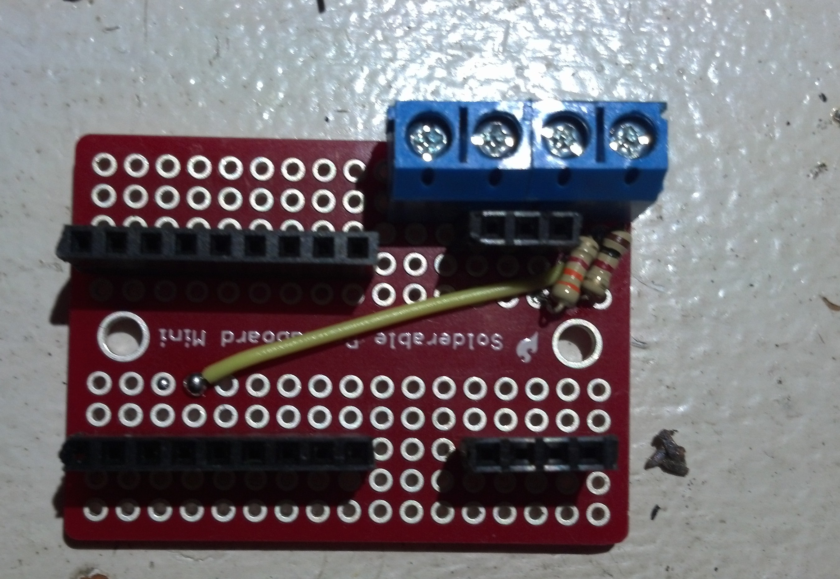
The brown wire is connecting analog 3(A3) of the Arduino to the Vout on the ACS712 Sensor.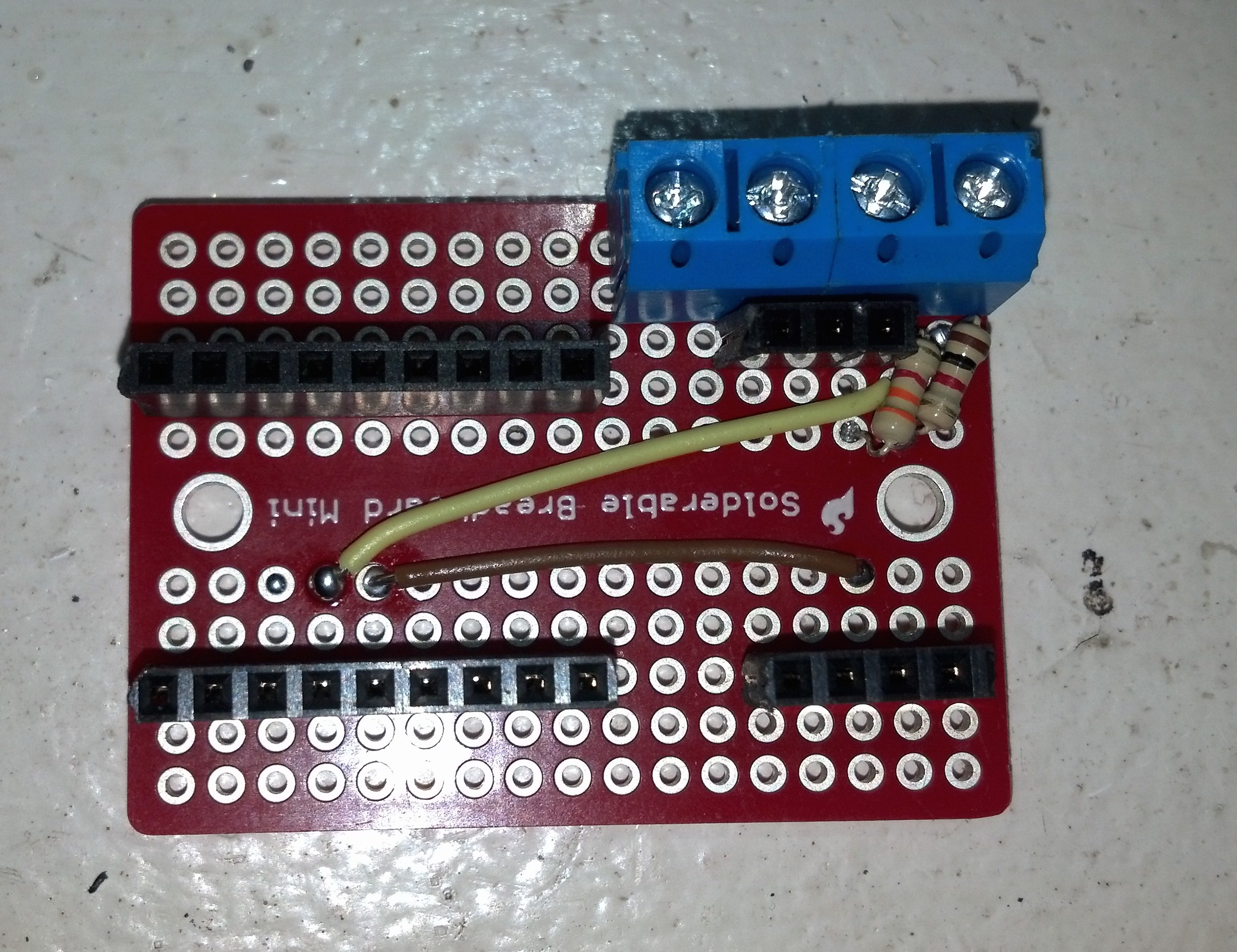
The second brown wire connects the Arduino’s VCC to the sensor. The bottom capacitor connects the sensors FILT to ground and the top capacitor connects VCC to ground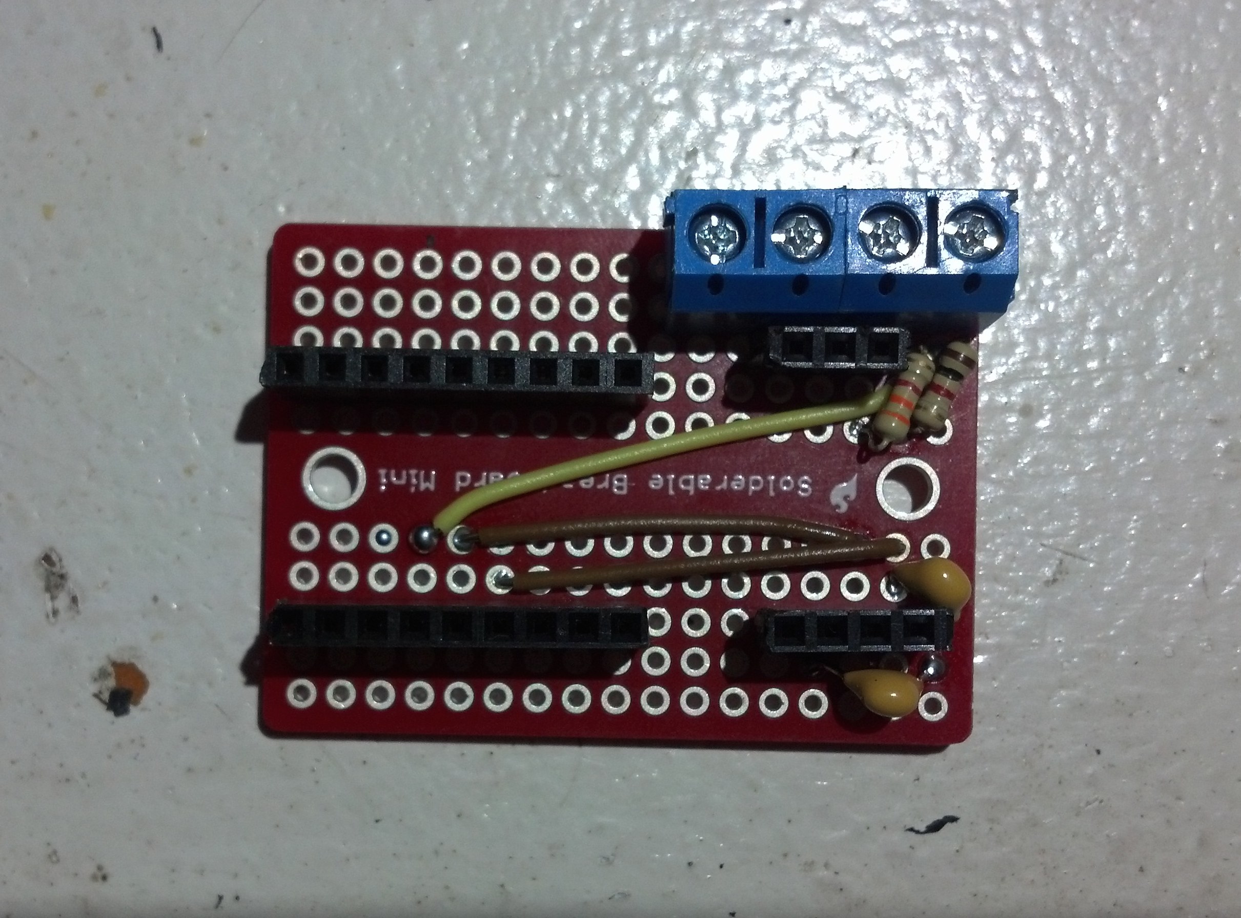
The Arduino being programmed with the code that is at the end of this post.
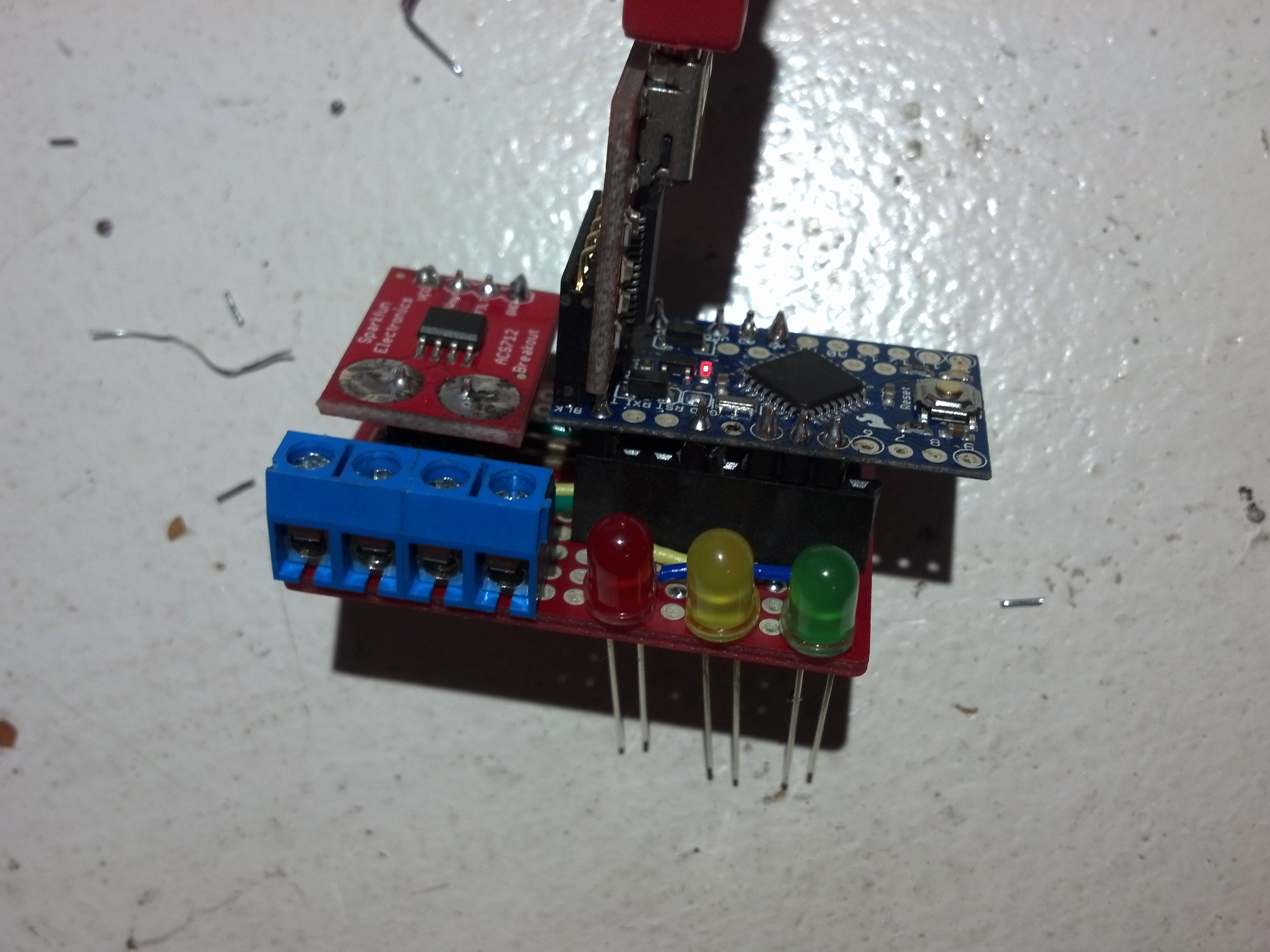
The finished device.
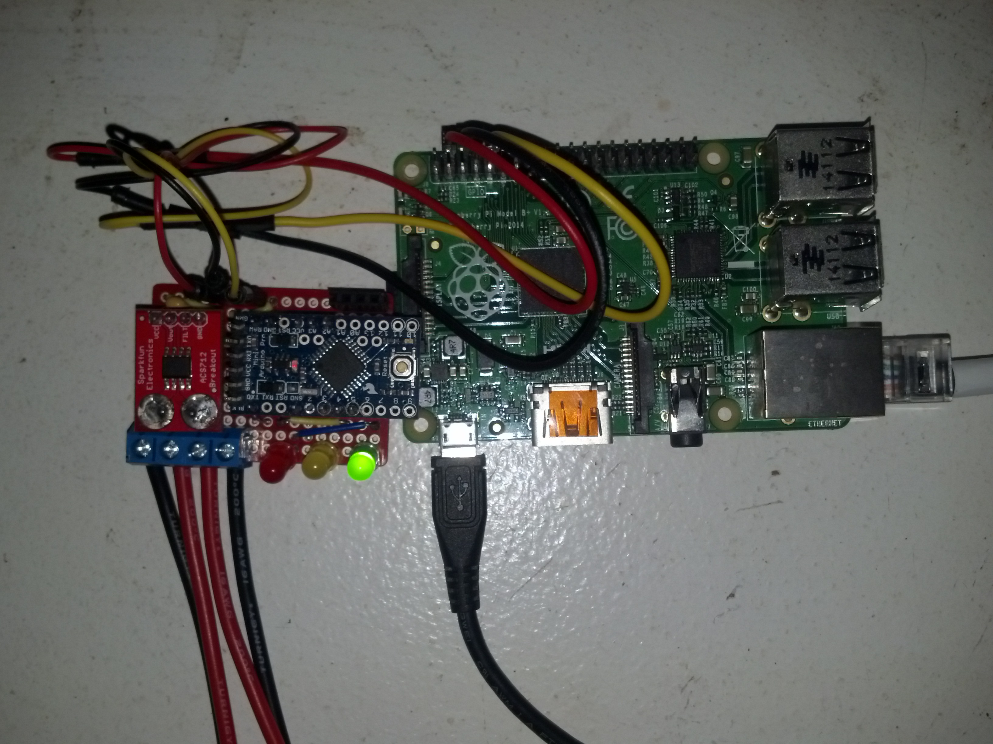
I added some headers on the board for the wires that go between the Arduino and Pi. The red wire “5V” goes from the 5V out on the Pi to the Raw input on the Arduino. The Black wire “ground” connects the ground on both components. The yellow wire is connected to the RX Serial GPIO pin on the Pi to the Arduino’s TXO pin. Since the Arduino operates at 3.3V we don’t need any kind of Logic Converter or step down. The serial pins can be connected directly.
Setting up the Raspberry Pi:
Pre-built image
Download the image form here.
Unzip it and use dd to write it to your SD Card
sudo dd if=IPWM.img of=/dev/mmcblk0 bs=4M
You can probable use Win32 Disk Imager, although it has not been tested.
Manual Installation
Here are the instructions if you want to start from scratch.
Prerequisites
- Raspbian Installed
- Access to the Pi, i.e., ssh
Enabling ssh login for root
By default the root user does not have a password, so you can not login to the Pi via ssh with the root account. To change this we need to login to the pi as the default user “pi” with the password “raspberry”
Once your logged in switch to the root user with the sudo command.
sudo su
Once your logged in as root, add a password for root using the passwd command
passwd
Follow the prompts to add a new password. You should now be able to login as root over ssh.
Enabling GPIO Serial Connection:
To enable the serial connection between the Arduino and Pi you’ll need to enable the serial connection on the Raspberry Pi. To do this we will need to edit the /boot/cmdline.txt file. First it’s a good idea to make a backup of the file.
sudo cp /boot/cmdline.txt /boot/cmdline.txt.old
Now edit the file with your favorite text editor.
vi /boot/cmdline.txt
and delete any instances of “ttyAMA0”
Here is what my file looked like originally.
dwc_otg.lpm_enable=0 console=ttyAMA0,115200 console=tty1 root=/dev/mmcblk0p6 rootfstype=ext4 elevator=deadline rootwait
When your finished the file should look something like this.
dwc_otg.lpm_enable=0 console=tty1 root=/dev/mmcblk0p6 rootfstype=ext4 elevator=deadline rootwait
Save and exit,
:wq
Installing Prerequisites:
- Raspbian
- MySQL
- PHP5
- php5-mysql
- Apache
- minicom
- RRDTool
apt-get upgrade
apt-get update
apt-get -y install apache2 mysql-server php5 php5-mysql minicom sendmail sendmail-bin rrdtool snmp snmpd snmp-mibs-downloader
Installing the IPWM files
The IPWM files include all of the files necessary for the Pi to collect and display the data acquired by the Arduino. Inside the archive are the web files, scripts for emailing, collecting data, creating graphs, the MySQL database, and an init.d file.
You can download the IPWM files from here or you can download them with wget.
Setting up the IPWM files
cd /root
wget http://www.incredigeek.com/home/downloads/ipwm/ipwm-1.0.tar.gz
tar zxvf ipwm-1.0.tar.gz
cd ipwm-1.0
mv home/ /var/www/
mv ipwm/ /
mv ipwmd /etc/init.d
chmod +x /etc/init.d/ipwmd
chmod +x /ipwm/scripts/*.sh
chmod +x /ipwm/email/*.sh
chmod +x /var/www/home/*.sh
Now edit /etc/rc.local
vi /etc/rc.local
and add the following line to the file so the ipwmd service starts on system boot. Make sure that it is above the line that says “exit 0”.
/etc/init.d/ipwmd start
Save and exit
:wq
Setting up MySQL
Lets create the MySQL database now.
login to MySQL as root
mysql -u root -p
and create a new database called wmdb.
create DATABASE wmdb;
Now create a new user “ipwm” who has privileges to the new database.
GRANT ALL ON wmdb.* TO ipwm@localhost ;
And close MySQL with ctrl+d.
Now we can import the sql file into our new database.
mysql -u root -p wmdb < wmdb.sql
You can test it by loging into MySQL with the new user.
mysql -u ipwm wmdb
and list the tables.
show tables;
You should see the following
mysql> show tables;
+----------------+
| Tables_in_wmdb |
+----------------+
| email          |
| settings       |
| unpw           |
| wm_data        |
+----------------+
4 rows in set (0.00 sec)
mysql>
Configuring and Setting up SNMP
The RRDtool uses SNMP to create the voltage graph.
Edit the snmpd.conf file in /etc/snmp
vi /etc/snmp/snmpd.conf
and add the following to the bottom of the file.
extend volt /ipwm/scripts/volt.sh
Setting up RRDtool
Create the directory for the RRDtool database.
mkdir /root/rrdtool
mkdir /root/rrdtool/volt
cd /root/rrdtool/volt
Now create the database with
rrdtool create volt.rrd \
--step 60 \
DS:voltage:GAUGE:120:0:10000000 \
RRA:MAX:0.5:1:1500 \
Final Steps
You should be all ready to go.
Go ahead and reboot your pi with
reboot
When it comes back up you can see if the services are running by using the ps command
ps aux | grep ipwm
You should also be able to access the webpage by going to ipaddressofpi/home
Screenshots
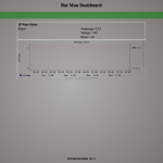
Arduino Programing
Arduino code.
/*
* Reads the voltage divider to calculate a battery voltage
* This software has no warranty, real or implied and is free to distribute and modify
*/

/*  The following code was used on an Arduino Pro Mini 3.3V from Sparkfun
Notice the ratio is 2.83 on a 3.3 volt arduino with a 3.3k and 1k resistors
*/

int led = 4;   // Red
int led1 = 3;  // Yellow
int led2 = 5;  // Green

int batMonPin = A2;   // input pin for the divider
int val = 0;          // variable for the A/D value
float pinVoltage = 0; // variable to hold the calculated voltage
float batteryVoltage = 0;
float ratio = 2.83;  // Change this to match the MEASURED ration of the circuit
// the ratio should be higher for a 5 volt Arduino


void setup() {

Serial.begin(9600);
pinMode(led, OUTPUT);
pinMode(led1, OUTPUT);
pinMode(led2, OUTPUT);

}

void loop() {
val = analogRead(batMonPin);    // read the voltage on the divider

pinVoltage = val * 0.00488;       //  Calculate the voltage on the A/D pin
//  A reading of 1 for the A/D = 0.0048mV
//  if we multiply the A/D reading by 0.00488 then
//  we get the voltage on the pin.

float average = 0;
for(int i = 0; i < 1000; i++) {
average = average + (.0264 * analogRead(A3) -13.51) / 1000;


delay(1);
}
Serial.print("Amperage: ");
Serial.println(average);
Serial.print(analogRead(A3));
Serial.println("Amp");

batteryVoltage = pinVoltage * ratio;    //  Use the ratio calculated for the voltage divider
//  to calculate the battery voltage
Serial.print("Voltage: ");
Serial.println(batteryVoltage);

//------- Watts -------
Serial.print("Watts: ");
Serial.println(average * batteryVoltage);

//WH AH -- To be continued

// LED's
if ( batteryVoltage <= 11.7 )
{
digitalWrite(led, HIGH);
digitalWrite(led1, LOW);
digitalWrite(led2, LOW);

}
if (batteryVoltage >= 11.7 && batteryVoltage < 12.10){
digitalWrite(led1, HIGH);
digitalWrite(led2, LOW);
digitalWrite(led, LOW);
}
if (batteryVoltage >= 12.10){
digitalWrite(led2, HIGH);
digitalWrite(led, LOW);
digitalWrite(led1, LOW);
}

delay(1000);
}
Ω