How to Disable the Bandwidth Server on Mikrotik/RouterOS

The Bandwidth test tool can be helpful to test speed between Mikrotik routers. But you can disable it if you don’t need it.

From Winbox

From Winbox click on Tools > BTest Server > Disable > OK

From Command Line

From the command line you can disable the bandwidth server by running the following command.

/tool/bandwidth-server/set enabled=no

If you are still on RouterOS 6.x use

/tool bandwidth-server set enabled=no

Enable Bandwidth test

If you need to enable the bandwidth server again, just change enabled=no to enabled=yes

/tool bandwidth-server set enabled=yes

https://grohler.com/disable-mikrotik-bandwidth-btest-server/

Install and Setup Tailscale on Ubuntu

Add the Tailscale package

curl -fsSL https://pkgs.tailscale.com/stable/ubuntu/lunar.noarmor.gpg | sudo tee /usr/share/keyrings/tailscale-archive-keyring.gpg >/dev/null
curl -fsSL https://pkgs.tailscale.com/stable/ubuntu/lunar.tailscale-keyring.list | sudo tee /etc/apt/sources.list.d/tailscale.list

Update and install Tailscale

sudo apt update && sudo apt upgrade
sudo apt install tailscale
sudo tailscale up

You’ll be given a link to visit to authenticate the device.

You can check the Tailscale IP address with

tailscale ip -4

https://tailscale.com/kb/1275/install-ubuntu-2304

View Fiber SFP details in Mikoritk RouterOS

Quick and simple way to check the details on a fiber SFP on a Mikrotik router. Replace sfp1_name with the SFP name or leave out the name and select a number.

/interface ethernet monitor "sfp1_name"

Results

                      name: sfp1
                    status: link-ok
          auto-negotiation: done
               full-duplex: yes
           tx-flow-control: no
           rx-flow-control: no
               advertising: 
  link-partner-advertising: 
        sfp-module-present: yes
               sfp-rx-loss: no
                  sfp-type: SFP-or-SFP+
        sfp-connector-type: LC
       sfp-link-length-9um: 3000m
           sfp-vendor-name: UBNT
    sfp-vendor-part-number: UF-SM-1G-S
         sfp-vendor-serial: FL31F80285729
    sfp-manufacturing-date: 20-02-20
            sfp-wavelength: 1550.32nm
           sfp-temperature: 64C
        sfp-supply-voltage: 3.23V
       sfp-tx-bias-current: 30mA
              sfp-tx-power: -5.254dBm
              sfp-rx-power: -4.1dBm
           eeprom-checksum: good
                    eeprom: 0000: 01 02 03 00 00 00 00 00  00 00 00 .....

How to Install Mikrotik RouterOS on VirtualBox


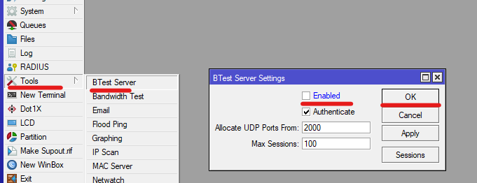
Note that there are a couple of limitations of using the Cloud Hosted Router (CHR). The main issue is that the default license doesn’t allow for more than 1Mbps on each interface.

https://help.mikrotik.com/docs/display/ROS/Cloud+Hosted+Router%2C+CHR#CloudHostedRouter,CHR-CHRLicensing

Download the VDI version of CHR from the Mikrotik downloads page.

https://mikrotik.com/download

Mikrotik has instructions for installing CHR in VirtualBox, so this post is more of just a summary.

https://wiki.mikrotik.com/wiki/Manual:CHR_VirtualBox_installation

  1. Create a VM with Type Linux, Version Other Linux (64-bit)
  2. While setting up the VM, select the VDI downloaded from Mikrotik as the virtual disk.
  3. Start the VM and login with admin for the username and nothing for the password.

The easiest way to spin up more vm’s to right click on the VM and Clone.

How to Create WireGuard Point-to-point Between Mikrotik Routers

We’ll create a tunnel between two Mikrotik RouterOS routers. Once we have the tunnel connected, we can then route traffic between them.

Note: You can add Preshared keys, but we don’t cover that in this post, just to keep things simple. Check out the following post if you want to add Preshared keys.

How to Create a Preshared Key for Wireguard

Here is how we will want our routers set up. The WireGuard PtP IP is the IP addresses used on both ends of the tunnel. The WAN IP is the IP of each Router. Local IP on Host B is setup to distribute DHCP.

Host A

WAN IP: 172.16.0.1
WireGuard PtP IP: 10.1.1.1/30

Host B

WAN IP: 10.0.0.2
WireGuard PtP IP: 10.1.1.2/30
Local IP: 192.168.0.1/24

We need Host A to be able to access Private IP’s (192.168.0.0/24) behind Host B.

We’ll pretend that the 172.16.0.1 address is a public IP, and Host B, is behind some sort of NAT network.

To create the Point-to-point, or PtP, we will create a WireGuard VPN tunnel, and then add routes from Host A to Host B.

For each Mikrotik we need to create a WireGuard interface, and then a peer. One of the peers needs a keep alive if we are behind a NAT.

Wireguard Setup Overview

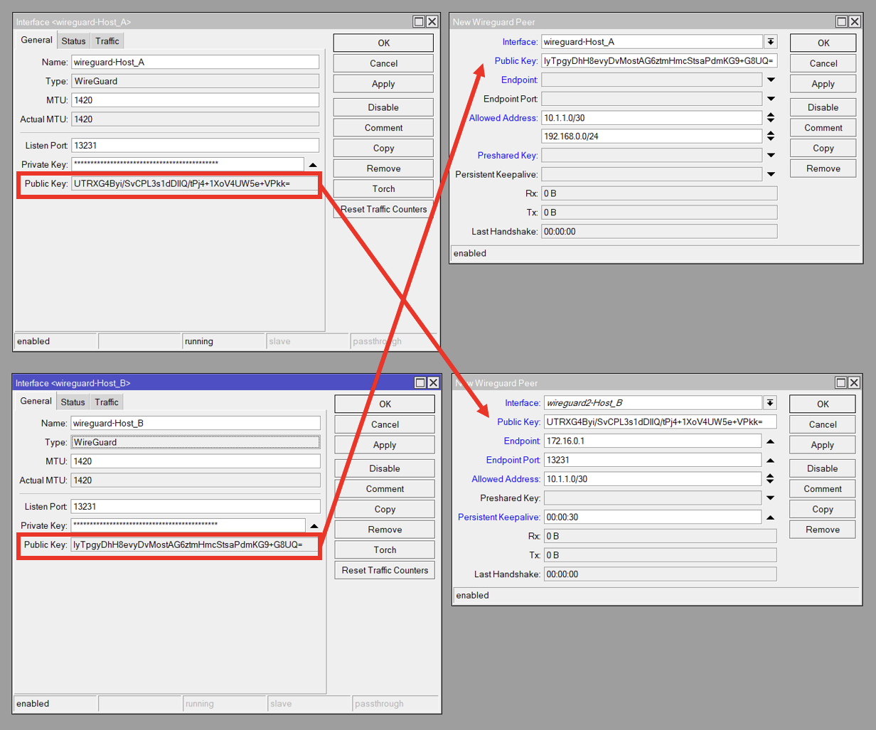
Here is an overview screenshot of what our WireGuard settings will look like. Host A is on top, and Host B on the bottom. On the left are the WireGuard interfaces, and the right contains the Peers.

We copy the Public Key from the remote WireGuard interface, to the Public Key on the local Peer. I.e. The Host_B Peer contains Host_A’s Interface Public Key and vice verse

Host A

If you want to, you can use the WinBox GUI to setup and configure the router.

Create the WireGuard interface

 /interface/wireguard/add name=wireguard-Host_A disabled=no

Add IP address 10.1.1.1/30 to the newly created WireGuard Interface in /IP/Address

/ip/address/add address=10.1.1.1/30 interface=wireguard-Host_A disabled=no

Create WireGuard Peer, WireGuard -> Peers

  • Select the WireGuard interface,
  • In the Allowed Addresses, put 10.1.1.0/30 and 192.168.0.0/24*.
  • Finally, put in the Public Key from Host B.
    Note that we can’t do this until we create the WireGuard Interface on Host B, so you’ll need to come back for this step.
interface/wireguard/peers/add interface=wireguard-Host_A public-key=HOST_B_WG_PUBLIC_KEY allowed-address=10.1.1.0/30,192.168.0.0/24

Add route for 192.168.0.0/24 to point to 10.1.1.2

/ip/route/add dst-address=192.168.0.0/24 gateway=10.1.1.2

*The Allowed Address sets which addresses work on the other side of the tunnel. If we don’t specify 192.168.0.0/24, then we won’t be able to route to those addresses. If we don’t add 10.1.1.0/30, then our tunnel won’t work at all. Since we only need to route to the 192.168.0.0/24 network from the Host A side, we don’t need this IP range on Host B.

Host B

Create the WireGuard interface, WireGuard -> Add

 /interface/wireguard/add name=wireguard-Host_B disabled=no

Add IP address 10.1.1.2/30 to the newly created WireGuard Interface in /IP/Address

/ip/address/add address=10.1.1.2/30 interface=wireguard-Host_B disabled=no

Create a WireGuard Peer, WireGuard -> Peers

  • Select the WireGuard interface,
  • In the Allowed Addresses, put 10.1.1.0/30
  • Finally, put in the Public Key from Host A.
/interface/wireguard/peers/add interface=wireguard-Host_A public-key=HOST_A_WG_PUBLIC_KEY endpoint-address=172.16.0.1 endpoint-port=13231 allowed-address=10.1.1.0/30 persistent-keepalive=00:00:30

Conclusion

That should be it. Verify that there is a connection. From Host A, ping 192.168.0.1 or any other remote device.

Troubleshooting

Unfortunately, there appear to be some wonky bugs with WireGuard on RouterOS. It does appear to be getting better, but here are a couple things to check if the tunnel is not connecting.

  1. Verify that the Firewall is not blocking WireGuard. You can allow the WireGuard port in the Firewall.
  2. Try disabling and re-enabling the Interfaces and/or Peers
  3. Verify that all the routes for the PtP are in /ip/routes. If not, try manually adding the route (10.1.1.0/30) on the WireGuard interface on both routers.
  4. Add a keep alive if a router is behind a firewall/NAT.
  5. Reboot and or Upgrade the RouterOS version and firmware.

Configure SNMPv3 on Cisco Router

https://www.cisco.com/c/en/us/td/docs/ios-xml/ios/snmp/configuration/xe-16/snmp-xe-16-book/nm-snmp-cfg-snmp-support.html

How to configure SNMP v3 on Cisco Switch, Router, ASA, Nexus (bestmonitoringtools.com)

Enter configuration mode

enable
conf t

Everything in bold you should look at changing.

snmp-server view ViewDefault iso include
snmp-server group GroupName v3 priv read ViewDefault
snmp-server location address
snmp-server user MyUsername GroupName v3 auth sha AuthPass1 priv aes 128 PrivPass

Exit and save changes

exit
write

Now we can verify the snmp details with

show snmp

Setup Remote Syslog on Cisco

Configure Logging

First we need to drop into configuration mode

conf t

Now we run the following command. Change ip-address to the address of you remote syslog server.

logging host ip-address

You will want to make sure that your time/timezone is correct.

https://community.cisco.com/t5/networking-knowledge-base/how-to-configure-logging-in-cisco-ios/ta-p/3132434

Set timezone

Change UTC and 0 to your your timezone and how many hours off UTC you are. For example for EST you would do EST -5

clock timezone UTC 0

Cisco, Reload in X Minutes and Canceling

Cisco’s can be rebooted with the reload command. The reload command allows you to specify how many minutes like

reload 5

to reload in 5 minutes. We can also reload at a specific time. For instance

reload 13:30

will reload the router at 1:30PM.

For a Cisco config to remain permanent, we have to “write” i.e. save the config. By default, making changes, for instance an IP address on an interface, will get wiped on a reboot or reload.

We can take advantage of this behavior to “test” changes on a Cisco router.

Example:

  1. Run the command “reload 10” to reboot the router in 10 minutes. The plan is to cancel the reload after making sure our changes work
  2. Make the needed changes to the Router.
  3. After verifying that everything is working, run the “reload cancel” command to cancel the reload
  4. Now we can run “write” to save our new config

To recap reload 10 will reload a router in 10 minutes
If we loose access to the router while making changes, once 10 minutes has expired, the router will reload, returning it to the last know working state.
The reload cancel command will cancel the reload.
write will make our config persistent across reboots/reloads

https://superuser.com/questions/1080513/cisco-router-auto-restart-in-x-seconds

Simple OSPF between Mikrotik Routers

https://help.mikrotik.com/docs/display/ROS/OSPF

Setting up OSPF between Mikrotik routers is not too difficult. The following commands should work with RouterOS version 7+. Run these commands on each Mikrotik changing out the router-id.

Create a Loop-back interface

First it would be a good idea to create an loopback interface that will stay up. We’ll use this address as the router-id. This should be unique per router.

/interface/bridge/add name=loopback
/ip/address/add address=1.2.3.4 interface=loopback

Now lets setup OSPF.

Create OSPF Instance

First we’ll create the instance. Use the address from the above loopback address. Technically you can use whatever id you want as long as it is a 32 bit “address” and is unique.

/routing/ospf/instance/add name=default router-id=1.2.3.4

IMPORTANT NOTE: If this router is also the default gateway, you’ll need to specify the “originate-default=always” option to share the default gateway over OSPF to the other routers. You don’t have to do this if you don’t want to share the default route.

Create OSPF Area

Now we can create an OSPF area. For a simple OSPF setup, we’ll just use the default 0.0.0.0 area.

routing/ospf/area/ add name=default area-id=0.0.0.0 instance=default

Create Instance

Now we can add an instance. This is responsible for what networks get shared with OSPF. If you want to do all the addresses on the router, then use 0.0.0.0/0. If you only want to do specific networks, run an entry for every network, changing 0.0.0.0/0 to the network of interest.

/routing/ospf/interface-template/add networks=0.0.0.0/0 area=default

Wrapping Up

After that we can check to make sure things worked.

/routing/ospf/neighbor/print

You should see at a neighbor. It can take a little bit for the neighbors to show up.

You can also check the routes on the router.

/ip/route/print

OSPF has a default distance of 110, so checking the routes is a quick way to verify the routes are getting updated. Do note that if you have a static route in with a lower distance, that will take precedence over OSPF.